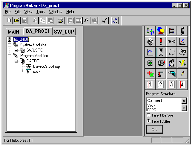
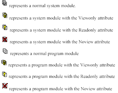
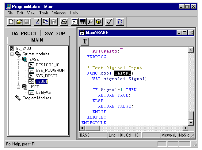
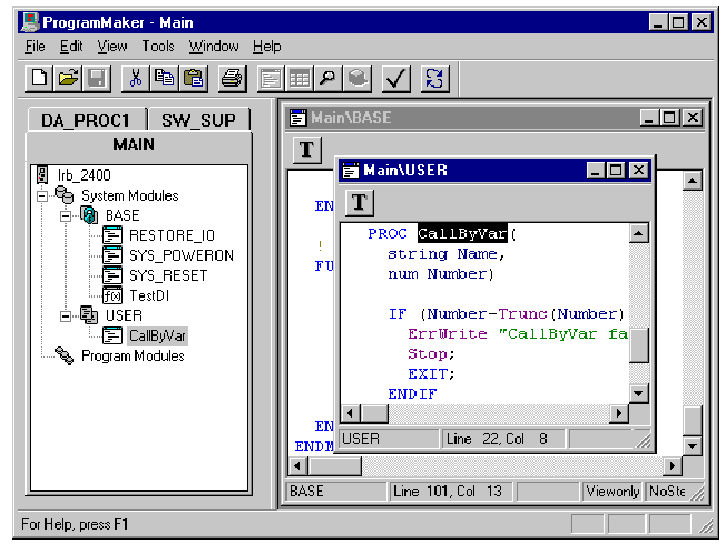
When you delete a
module, it is permanently removed from the system. You cannot retrieve the
module after it is deleted. To avoid unwanted deletions, you can choose to have
ProgramMaker prompt you for confirmation whenever you try to delete a module. To
do this, set ProgramMaker’s options to Confirm
on Delete.
Note: You cannot delete
a module if the Read only or View only attributes
are present.
To delete a module, first
select the module you want to delete in the Program Tree.Then do one of the
following:
1. Select Edit/Delete from the Menu Bar.
2. Press Delete at
the keyboard
3. Select Delete
Module from the
context-sensitive popup menu
Saving a program causes the contents of all loaded program
modules to be saved into a single program file. System modules are not saved
along with the program modules.Saving
a module causes the contents of the single selected module to be saved to a
module file.You save a program by selecting the program module in the Program
Tree, followed by invoking the File/Save
As or File/Save commands.If you choose File/Save,
ProgramMaker saves the program to a file using the name of
the program currently loaded. If no name is available, then ProgramMaker uses
the name of the selected program module, but with the .prg
file extension.If you choose File/Save
As, you see the following
standard Windows File Save dialog:
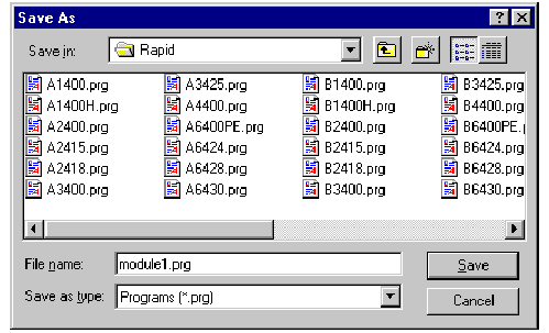
The system provides a default filename that is the name of the
program currently loaded. If no name is available, then the system proposes the
name of the selected program module. If you instead want only to save the
selected module rather than the entire program, change the file type from Programs
(*.prg) to Modules
(*.mod) in the Save
file as type: control of the
dialog. When you select File/Close,
all currently loaded program modules are unloaded. System modules, however,
remain loaded. If you close before saving the program, ProgramMaker prompts you
to save your work. Programs are closed automatically when you exit ProgramMaker.
RAPID modules consists of
zero or more data declarations and zero or more routine declarations. You create
and work with routines in much the same manner as you create and work with
modules.
CREATING NEW ROUTINES
To insert a routine into a module, select a module in the
Program Tree and do one of the following:
1. Press the Insert key on your keyboard
2. Select the Edit/Insert
command
3. Select the Insert
New Routine from the context
sensitive popup menu.
Any of these actions causes the
New
Routine Declaration dialog to
appear:
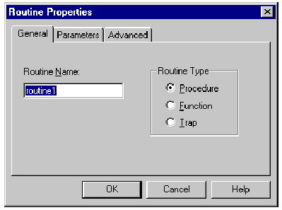
The New Routine
Declaration dialog is a tabbed
dialog. The General tab
allows you to set the name and type of a routine. The Parameters
tab allows you to set the
routine parameters. You can use the Advanced
tab to set other routine
attributes. Refer to the next section, Viewing
Routine Attributes, to learn
about setting the attributes for a routine.
Note: You cannot create
or edit a routine if the Read
only or View
only attributes are present in
the module in which you are trying to add the routine.
VIEWING ROUTINE ATTRIBUTES
To view the attributes of an existing routine, select the
routine from the Program Tree and choose the Edit/Properties command from the Menu Bar or Properties
command in the context
sensitive popup menu. In either case, the Edit
Routine Declaration dialog
appears with the General tab
selected:A tabbed dialog is a dialog box with buttons along the top of the
window that are similar in appearance to file folder tabs. Related groups of
data are placed on individual pages.
There may be many pages in a
tabbed dialog. You click the tabs to switch back and forth between pages. Routine
Properties – General Page
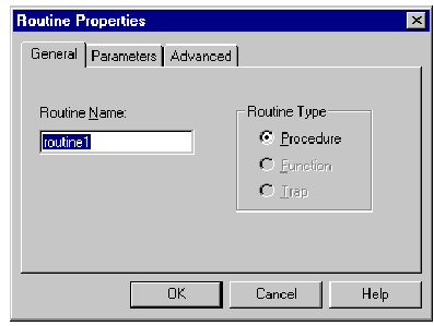
The first page displays general routine attributes: the routine
name, routine type, and return type (if applicable; procedures and traps have no
return type). The routine name is placed in a standard Windows edit control; you
edit the routine name simply by typing in a new name. You edit the routine type
by selecting available types from a combo box: Procedure, Function,
or Trap.The
return type applies only to functions and is the data type the function will
return.This edit control is hidden for procedures and traps. You enter a data
type into the edit field using the dropdown list box which displays a list of
all valid data types available for assigning to the function.
Routine Properties – Parameters Page
You display the Parameters
page by selecting the Parameters tab. The Parameters
page displays the parameters
associated with the routine in a list box, as shown below:
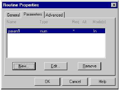
The headers in the list box show the meaning of the information
displayed in each column. The information shown is the parameter name and data
type, whether the parameter is Req(uired)
or Alt(ernate),
and the parameter transfer mode: In
(Transfer),
InOut, Var(iable),
or Pers(istent).
Creating Routine Parameters
You create a routine parameter by selecting the
New button at the bottom of the
dialog. This activates the New
Parameter dialog as shown
below:
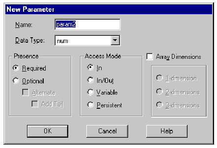
The many options available for parameter declarations are
logically grouped together. The Parameter
Data Type specifies the nature
of the value being transferred in the call argument. The Presence of a routine parameter may be Required
or Optional;
if required, the parameter must be supplied when the routine is called. If a
parameter is optional, it can be one of several Alternative
parameters; if Add
Tail is checked, it is the last
alternative. If a parameter is required, the Alternate
and Add
Tail attributes are
disabled.The Access Mode affects
the usability of the value within the routine; for example, the value can only
be read and not written if it has the In
attribute. A parameter is a
scalar unless the Array
Dimensions attribute is
checked; if an array, the parameter may assume a degree of dimensionality
between 1 and 3. The dimensions group is disabled unless the Array
Dimensions attribute is
checked.
Editing Routine Parameters
You edit a routine parameter by first double-clicking on the
parameter in the list box or by selecting the parameter and clicking the Edit
button at the bottom of the
dialog box. This activates a dialog similar to that shown below:
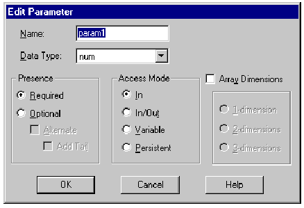
The parameter name is placed in a standard Windows edit control;
you edit the parameter name by typing in a new name. You choose the data type by
selecting the desired type using the dropdown list box. To create a switch
parameter, you select switch from
the dropdown list box.
Routine Properties – Advanced Page
You display the Advanced
page by selecting the Advanced tab. This page displays other
attributes associated with the routine, as shown below:
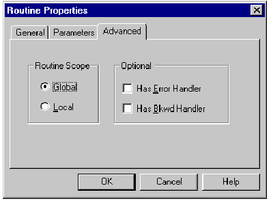
The Routine
Scope attribute specifies
whether the routine is visible only to other routines within the same module
(Local) or to all other routines in the system (Global). Global routines share
the same namespace as other global objects, such as modules or data; you must be
careful when naming global routines so that you don’t use the same name as
another global object.Certain routine types can contain additional instruction
sections: A Procedure can contain both an Error
Handler and a Backward
Handler, while a Function can
contain only an Error Handler,
so when you are editing a Function declaration, the Backward
Handler attribute is disabled.
CUTTING AND PASTING ROUTINES
The Cut Buffer
The Cut Buffer is
a mechanism that is used to temporarily store or make a copy of a routine. When
you want to move a routine from one module to another, you select the routine to
move, cut the routine to the Cut Buffer, and paste the routine into the
destination module from the Cut Buffer.
Cutting to the Cut Buffer
When you cut a routine it is placed in the Cut Buffer. To cut a
routine, first select the routine in the Program Tree. Then do one of the
following:
1. Select Edit/Cut.
2. Simultaneously press the
Ctrl and X keys on your keyboard.
3. Select Cut from
the context-sensitive popup menu.
Copying to the Cut Buffer
Copying a routine to the Cut Buffer places a copy of the routine
in the buffer without removing the routine from the module. To copy a routine,
first select the routine you want to copy. Then do one of the following: 1.
Select Edit/Copy 2.
Enter Ctrl-C at
the keyboard 3. Select Copy from
the context-sensitive popup menu Pasting
from the Cut Buffer Pasting a
routine from the Cut Buffer inserts the routine in the module you select. To
paste a routine, first select the module you want to receive the routine you
want to paste. Then do one of the following: 1. Select Edit/Paste
2. Enter Ctrl-V at
the keyboard
3. Select Paste
Routine from the
context-sensitive popup menu.
Chapter 3: Basic Operations
3-13
When you copy a routine into a module that already contains a
routine with that name, ProgramMaker automatically displays an ":x" next
to the routine name where the x is a number. For example, if the routine name is alpha,
the copied routine name is displayed as alpha:2.
DELETING ROUTINES
When you delete a
routine, it is permanently removed from the module. You cannot retrieve a routine after it is deleted. To avoid unwanted
deletions, you can choose to have ProgramMaker prompt you for confirmation whenever you try
to delete a routine. To do this, activate Confirm
on Delete in the ProgramMaker Options. To delete a routine, first select the routine you want to
delete. Then do one of the following:
1. Select Edit/Delete
2. Press Delete at
the keyboard
3. Select Delete from the context-sensitive
popup menu
Chapter 4
Program Editing
Viewing and editing the RAPID instructions that comprise modules
and routines is presented in this chapter. Viewing and editing routine and
module data declarations in spreadsheet format and graphical format is covered in Chapter
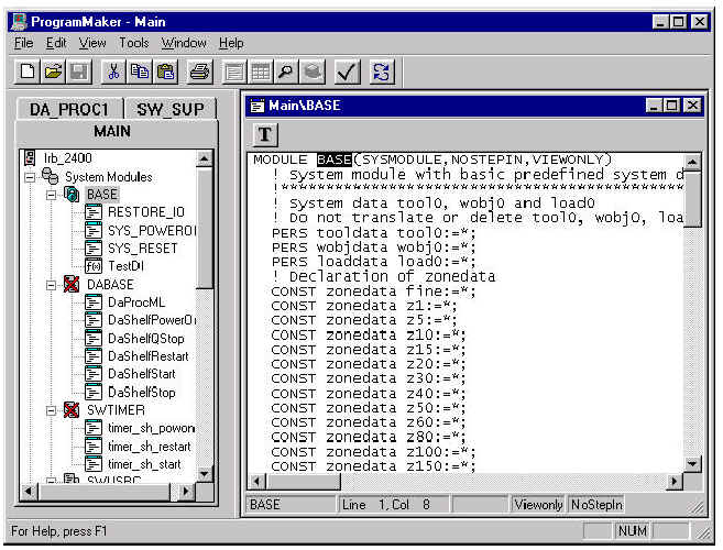
5 and Chapter 6.As discussed in the previous chapter, to view and edit RAPID
instructions, you View
the routine or module selected in the Program Tree. A window is
created displaying the instructions for the module or routine, as shown:
CHANGING THE FONT
You can select the font face and point size of the text that is
displayed within the window. ProgramMaker can also display syntax-sensitive
colorization of the
ProgramMaker User’s Guide
displayed RAPID code. This is called
Chromacoding.
Chromacoding allows you to display RAPID keywords in one color, while displaying strings
and other language elements in other colors. See Appendix A for detailed
instructions on setting these and other ProgramMaker options.
HOW PROGRAMMAKER
HANDLES INSTRUCTIONS
ProgramMaker does not treat the RAPID instructions as simple
lines of text. ProgramMaker is a instruction-oriented editor, meaning that it
deals instead with RAPID statements or statement components. This being so, it
guarantees that all statements you create are syntactically correct. You cannot
mistakenly enter misspelled RAPID keywords, nor can you enter a statement that,
for example, omits commas, semi-colons, or other required language elements.Because ProgramMaker prevents syntax errors, a RAPID program you
create with ProgramMaker will always load when you transfer it to your
robot. Generally, you create and edit statements using the Instruction
Picklist and dialogs described in the sections to follow. The Instruction Picklist
allows you to create the most common instructions with a single click of a button.
However, it is also possible to enter statements via the keyboard with conventional
text-based input.
Note: If ProgramMaker is configured for an M94A or V2.0 robot,
you are limited to entering no more than 200 characters at a time using text-based input. No
limit exists when configured for a V2.1 or later robot.
THE SELECTION CURSOR
When you place the mouse cursor on a statement or statement
component and press the left mouse button, that part of the statement is selected,
depending on the exact position of the cursor. A selected item is shown in
reverse-highlight.You can also move the selection left, right, up, or down using
the arrow keys. You can also use the Tab key in place of the right
arrow, and the SHIFT-Tab
combination in place of the left arrow Note that the Status Bar’s Row/Column Pane shows the beginning
position of the selection in row,
column format. At least one statement or statement component is always
selected.
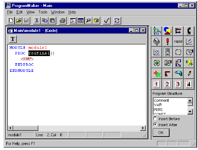
When you first open a routine window, the routine name is automatically
selected and highlighted as shown in the following diagram.
Because of the statement-oriented approach, the entire item that
is under the cursor when the mouse button is pressed is selected. You cannot,
therefore, select a single character "E" from the ENDFOR clause of an FOR...ENDFOR
statement (for example). When you place the cursor on the "E" and
click the left mouse button, you will select the entire ENDFOR
statement, as shown below, and
the system will "know" internally that you have focused on the ENDFOR
part of a FOR...ENDFOR
statement.
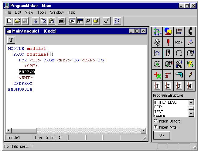
The part of the statement that gets selected depends on where
the cursor is placed. If, for example, you place the cursor on the FOR clause instead, the entire
FOR...ENDFOR statement
gets selected. Generally, whenever you place the cursor on a statement delimiter (white space, the terminating
semi-colon, or keywords), the entire statement is selected. You can also select an entire
statement by clicking the mouse outside the text boundaries; that is, on the blank space
to the right or to the left of the statement. Placing the cursor on a statement
component (argument, expression, etc.) generally selects only that component.
Multi-line selections
When you select a compound statement such as
FOR...ENDFOR,
the selection cursor automatically extends across multiple lines of RAPID
instructions to encompass the entire statement. You can also extend the
selection to span multiple lines for non-compound statements. One way of doing this is to hold the left mouse button down
while moving the mouse. The selection begins on the line where the mouse is
located when the button is pressed, and continues to the line where the mouse is located
when the button is released.
Chapter 4: Program Editing
You can also extend the selection by holding down the SHIFT key
on the keyboard while selecting with the mouse. The selection begins on the line
that held the selection before the SHIFT key was pressed, and ends on the line
where the mouse is located when subsequent selections are made with the SHIFT key
held.
Cancelling a multi-line selection
You can cancel a multi-line selection by pressing the ESCAPE
key. The selection then changes to the statement beginning at the first line of the
previous multi-line selection.
There are basically two ways of creating and editing RAPID
statements. Generally, you use the Instruction
Picklist and dialogs described
in the sections to follow. The Instruction Picklist allows you to create the most common
instructions with a single click of a button. With this method, as with the teach pendant
on the robot, you build up routines by inserting instructions that you pick from a list.
You then complete the statement by filling in the associated parameters.It is also possible to enter statements via the keyboard with
conventional text-based input. This second method is best suited for simple statements
and is also described below.
THE INSTRUCTION PICKLIST
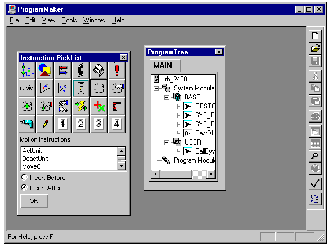
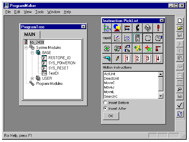
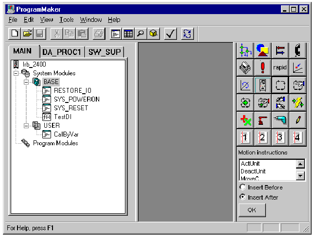
When you first start ProgramMaker, you see a display similar to
the following:
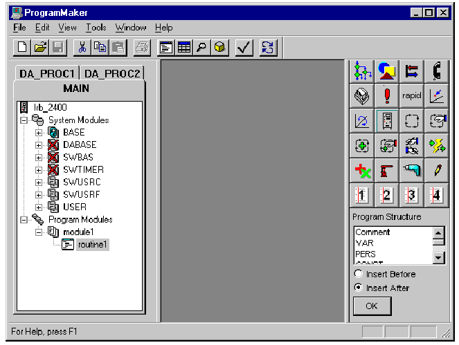
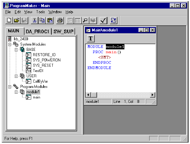
The Program Tree, shown on the left, presents a
hierarchical, diagrammatic view of the structure of all programs currently loaded in the robot
controller. The Program Tree is similar in function to the directory tree window of the
Microsoft Windows Explorer. For a more complete explanation, refer back to Chapter 2. The
Program Tree in the picture above shows a program module called module1 which contains a procedure
called
routine1. This
module and routine were created using the commands described in the previous chapter.The Instruction Picklist, which appears on the right, contains
all of the instructions that you can use in writing a RAPID program. Like the Program
Tree, the Picklist is a dockable window, which means you can move it around on
ProgramMaker’s screen and place it wherever you wish, or you can tear it off
and leave it float. For more information, refer back to Chapter 1.
The Instruction Picklist, when first initialized, looks like
that shown below left:
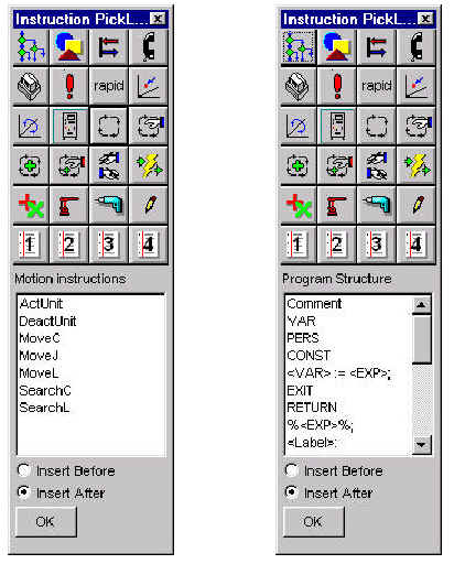
The buttons at the top of the Instruction are used to select the
groups of instructions that appear in the list below. The contents of the list changes
as you press the various buttons. The name, or classification, of the instruction group
appears just above the list. The Program
Structure instructions,
displayed when you press the button at the top left, is shown above on the right.
Note: Not all groups contain member instructions, depending upon
how you have configured your robot. For example, you will not have ArcWare instructions in
the lists of available instructions unless you have selected a configuration that contains the
ArcWare option. Refer to your DeskWare
User’s Guide for
further information on selecting and creating configurations.
All user-written instructions appear as part of the
Common group associated with the button that has a pencil icon on its face. Any procedure,
function, or trap routine that you write appears in this list There are four user-definable instruction lists that are
associated with the bottom row of buttons shown in the pictures above. See Appendix A for
detailed information on creating these lists.
INSERTING INSTRUCTIONS
WITH THE INSTRUCTION PICKLIST
You must have a view containing RAPID code activated before you
can use the Instruction Picklist. In the example below, the view is set to
the module called module1 as shown in the Program Tree in the picture above.
Subsequent example displays do not include the Program Tree in order to make more
space available for the view of the RAPID code.
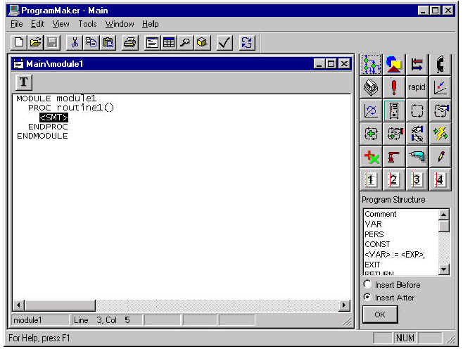
You use the Instruction Picklist to insert a statement by
selecting an instruction from the list and pressing the OK button; alternately, you can
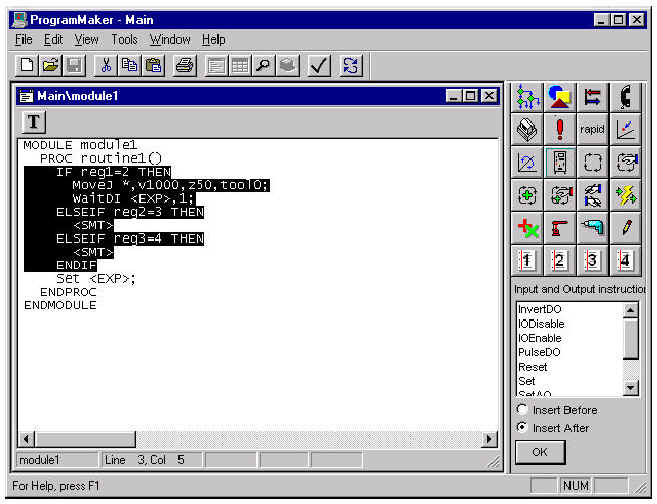
simply double-click the selected instruction. Inserting a IF...THEN...ELSE statement into the routine window shown above yields the following result:
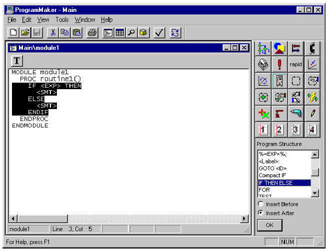
The entire body of the IF
statement is inserted in place
of the <SMT> placeholder. If you now insert another instruction, it will be either above or
below the current instruction, depending on whether you have the Insert
Before or Insert
After radio button checked on the Instruction Picklist. Note: You cannot insert data declarations into <SMT>
placeholders, nor can you insert executable RAPID statements into <DDN>
placeholders. If you want to insert a data declaration (available in the Program Flow instructions),
in a routine or module where no <DDN> placeholder exists, select the
routine or module before choosing the data declaration from the Picklist. Similarly, if
you want to insert an instruction into a routine where no <SMT> placeholder
exists, select the routine before choosing the statement from the Picklist. You cannot
insert executable statements into a module. The inserted IF statement
itself contains several placeholders: two <SMT> and one <EXP>. You can expand a <SMT> placeholder by
selecting only the <SMT> placeholder and inserting another instruction. For instance, if you select the first <SMT> PHR and insert
a MoveJ instruction,
you see the following screen:
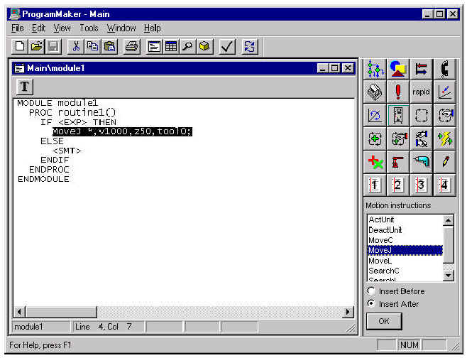
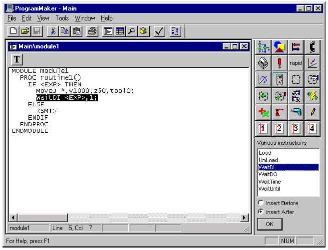
Inserting another
instruction at this point yields, for example, the following result:
If you want to insert another instruction after the
IF statement, you must move the selection to the IF statement itself by clicking
over the IF, THEN, or ELSE
components. This selects the entire statement; you can also
select the entire statement by clicking over the white space between and around
the keywords. You can also select just the <EXP> PHR or the ENDIF
clause; ProgramMaker
"knows" that these are parts of the IF
statement. Selecting one of the IF
statement’s parts and
inserting an instruction results in the following screen: 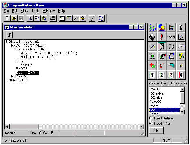
INSERTING INSTRUCTIONS
AS TEXT
It is possible to enter instructions through the keyboard as
text if you don’t want to use the Instruction Picklist.
Note: If ProgramMaker is configured for an M94A or V2.0 robot,
you are limited to entering no more than 200 characters at a time using text-based input. No
limit exists when configured for a V2.1 or later robot.
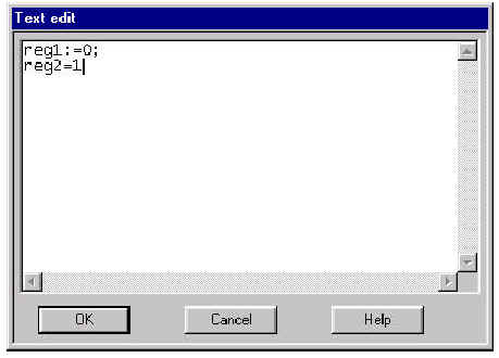
The Text Edit Dialog
To enter an instruction as text, choose
Edit/Insert or the context-sensitive popup menu. The following Text
Edit dialog appears, with
sample text already inserted:
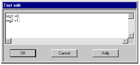
You can type any number of valid RAPID statements into the edit
control; when you press Enter,
the text is interpreted, and, if valid, inserted into the routine. The Text Edit dialog can be resized and moved about on your
screen; next time you invoke it, the previous size and screen position are recalled.
HOW ERRORS
IN TEXT ARE HANDLED
ProgramMaker will never allow you to enter statements that are
not syntactically valid.
If you make a typographical error while inserting a statement as
text using the method described above, the system will detect the error as it
tries to interpret the text into RAPID instructions. Suppose, for instance, that we
forgot both the colon ":" and
the semicolon ";"
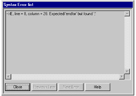
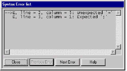
in the second assignment statement above. ProgramMaker responds by presenting an
Syntax
Error list dialog, shown
immediately below, containing the errors that were found.
Note: The first time the Syntax Error list dialog appears on
your screen, it may overlap the Text edit dialog. You can change the size of the Syntax Error list dialog
and place it anywhere on your screen.The next time the dialog appears on the screen, it remembers
where you last left it.
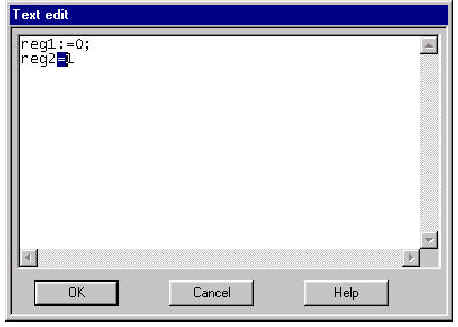
The exact location of the first error is highlighted in the Text
edit dialog.
Note: This output was generated with ProgramMaker configured to
use an V3.0 version controller.The error statements generated by earlier controller
configurations may differ somewhat in contentfrom those generated by V3.0.
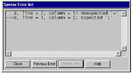
To highlight the subsequent error, you press the Next Error
button in the Syntax Error list dialog; the appearance of the two dialogs changes as
shown below:
You can correct the error by re-typing the statement in the Text
edit dialog while the Syntax Error list dialog is on the screen. After you make the
corrections, press the OK button in the Text edit dialog. If you corrected all of the
errors, both dialogs will close and the text you edited will be entered into the RAPID
program.
ProgramMaker provides a number of instruction-specific dialogs
to help guide you in making changes to existing RAPID instructions; alternately,
you can directly edit RAPID statement components via keyboard input. Both methods are
described in the following sections.
DEFAULT PARAMETER HANDLING
As you create instructions using the Instruction Picklist, some
statements are automatically populated with default parameters and values. For
example, when the
MoveJ instruction
was inserted in the above example, the four required parameters of the statement (ToPoint,
Speed, Zone, and Tool)
were given values of a robtarget
literal, v1000, z50,
and tool0.
The WaitDI instruction,
by comparison, was only given a value for its Value
parameter; the expression placeholder, <EXP>, for the
Signal parameter was left unmodified. The system has many built-in rules
that automate the creation of
default parameters for various instructions; ProgramMaker utilizes these rules
during creation of statement instructions. While sometimes these rules may provide
satisfactory default values, you may want to change them; and of course you want to
add real values in place of <EXP> placeholders.
After you have entered an instruction, you may also want to
change it’s overall structure. For example, you may want to add optional parameters
to a MoveJ
statement, or you may want to add Elseif clauses to an IF statement.
EDITING WITH INSTRUCTION DIALOGS
To edit a statement via a dialog, you select the
Properties command either from the main or context-sensitive popup menus. You can also double-click
on the statement. Each type of statement incorporates a unique dialog that is
specifically designed for editing that statement.
Editing an IF...THEN...ELSE statement
For the IF...THEN...ELSE
statement, you get the
following dialog:
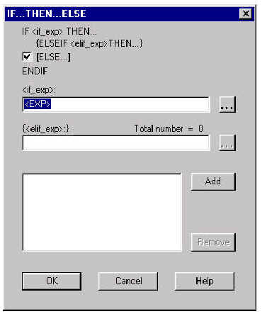
Within this dialog, you can view and change the structure of the
IF statement.
The overall structure of an IF statement is presented at the
top of the dialog. The check box next to the [Else...]
text indicates whether or not
the statement has an ELSE
clause. The total number of ELSEIF clauses is indicated to the
right of the {ELSEIF <elif_exp> THEN...} text;
in this case there are none. You remove the ELSE
part by unchecking the box next
to the [Else...] text; conversely, checking the box adds it back in. You add
Elseif
clauses by pressing the
Add button, and
remove them with the Remove button.
If the Add button
is pressed
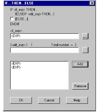
The total number of ELSEIF
clauses is reported at the top
of the dialog, The list box near the bottom of the dialog shows the expressions for each
ELSEIF clause; the
ELSEIF expression
that is currently selected within the list box for editing is reported next to the edit control, which is where you type the
actual expression. The upper edit control is used for typing the expression for the
IF
test. Examine the following entries for this dialog:
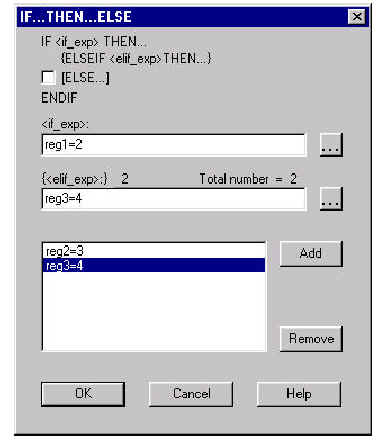
After pressing OK,
the IF statement
in the routine window is updated as shown below:
If you make an error inputting an expression in a dialog, it is
identified as a syntax error and reported to you in the Syntax Error list dialog
described in the How Errors in Text Are Handled section
above. No changes are made to the expressions until you correct the errors. If you want assistance in creating the expressions that go into
the <EXP> placeholders, select the more button(…) to the right of the
edit control in the dialog.
This brings up the Expression Editor dialog, as shown below:
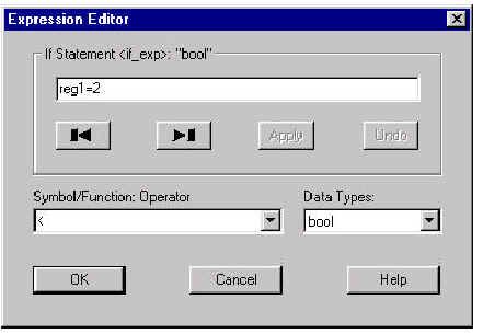
For detailed instructions on using the Expression Editor, see
Appendix B.
Editing a Procedure Call statement
If you Edit/Modify a procedure call – for
example, the MoveJ statement
within the
IF statement
– the Procedure Call dialog
appears as shown:
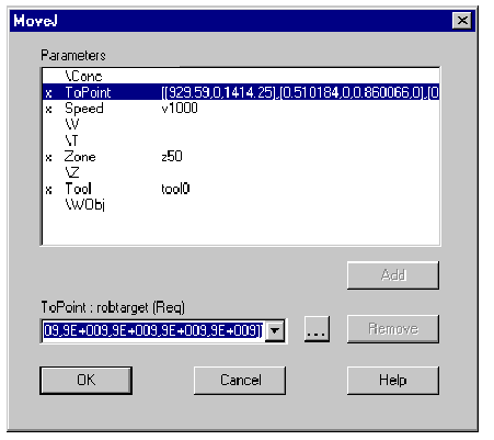
The name of the instruction ( in this case
MoveJ)
appears in the title bar of the dialog.The parameters used by the procedure appear in the upper list
along with their current values. An ‘x’ preceding a parameter name indicates
that the parameter is present; optional parameters, if not present, will not be so
marked. The ToPoint parameter
is highlighted because, in this example, the dialog was invoked by double-clicking on this parameter. The highlight is
always placed on the parameter that is under the mouse cursor when the double-click
occurs. If you double-click on the MoveJ,
however, the highlight will be moved to the first available present parameter. You use the combobox control at the bottom of the dialog to edit
the parameter selected in the list. Just above the combo box, the parameter
name (ToPoint)
and type (robtarget)
are displayed. The (Req) indicates
that this is a required parameter; optional parameters are indicated by
(Alt).
To enter another value, you can for example simply type a value in the edit window, or browse for
available robtarget symbols by invoking the Expression Editor described above.
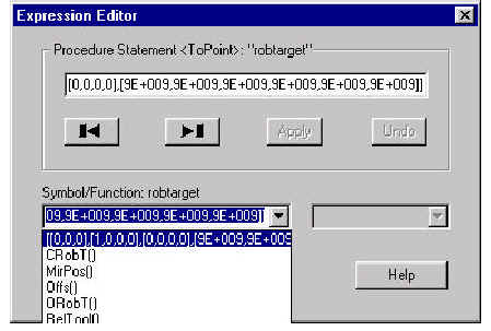
The dropdown list for the ToPoint
parameter contains both
available data and
functions that are visible from this
MoveJ instruction. Note that
functions appear
with a trailing "( )". You change the
ToPoint value either by typing a new
argument
into the edit control or by selecting an item from the list.
Selecting Offs() invokes
the
following Function dialog:
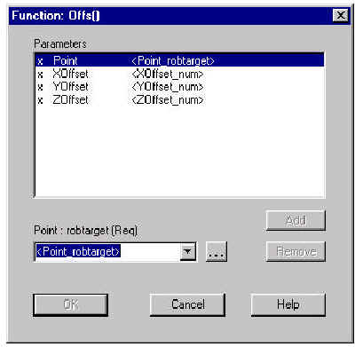
Default values are inserted for function arguments. You change
these arguments by
typing new ones within the edit control or selecting new ones
from the drop-down
list.
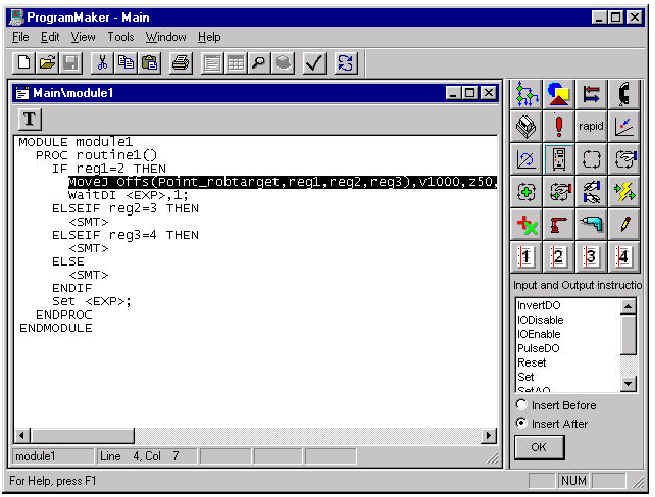
Pressing OK repeatedly
to exit the Function dialog, the Expression Editor, and the
Procedure dialog modifies the
MoveJ statement in the routine window
as shown
below:
4-23
Editing optional parameters
Some procedure call instructions, such as
MoveJ,
can be supplied with optional parameters. In the MoveJ
Procedure Call dialog, all
available parameters that can be supplied to the call are displayed in the upper listbox.
Optional parameters are indicated with a ‘\’; the absence of an ‘\’ indicates a
required parameter. If an optional parameter is present,
(that is, currently being supplied to the procedure call), it is marked with an ‘x’ and its current value is also
displayed. Required parameters are always present. To add an optional parameter, first select the parameter in the
list. As shown below, when the \WObj parameter
is selected, the Add button
to the right of the listbox becomes enabled.
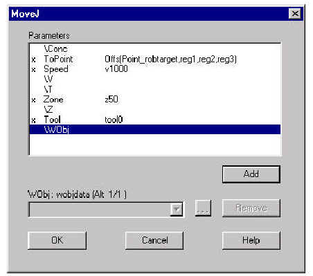
After you press the Add
button, the \WObj parameter is marked as present,
and the combobox is enabled and initialized with valid
wobjdata
symbols. You can then select a value for the \WObj
parameter with the Expression
Editor. See Appendix B for further details.
Note that some parameters, such as
\Conc,
are dataless switches. The combobox remains disabled in such a case.Note also that after you add the optional parameter, the
Add button becomes
disabled, while
the Remove button
becomes enabled. You use the Remove
button to remove optional parameters from the set of currently present
parameters. The Add and Remove buttons
are always disabled whenever you select one of the required parameters from the listbox, since required parameters
must always be present.
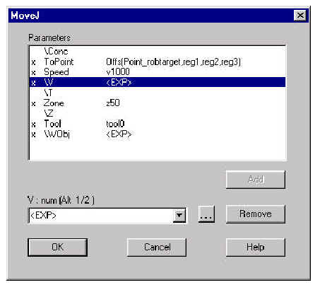
A MoveJ instruction
contains optional parameters named \V and \T
that are
mutually exclusive alternates;
that is, the presence of one of the excludes the presence of the other. If you want to add the
\T parameter, but the \V
parameter is already present, the system will not let you add
\T
until you first remove the \V
parameter.
Mutually exclusive parameters are identifiable from the data
type descriptor just above the combobox; for example, if you select
\V,
the indicator contains
V : num (Alt 1/2).
This means that \V is
the first mutually exclusive alternate in a group of two possible alternates. Alternates are always grouped
sequentially.
4-25
Editing other Instructions
Almost every other RAPID instruction uses one of the many custom
dialogs to present the means for guided editing of the instruction’s
components. See Appendix B for descriptions of the other instruction dialogs. The
exceptions to this are Comments, Labels, and Goto statements. You edit these statements
with the text editing method described in the following section.
EDITING INSTRUCTIONS
AS TEXT
If you want to quickly modify an instruction or group of
instructions directly as text, first selecting the statements you want to edit and choose the
Edit/As
Text
command from either the main or the context-sensitive menus.The following rules apply to editing statements as text:
· You cannot
select and text edit entire modules; you can, however select and edit entire routines.
· You cannot
select and text edit multiple routines simultaneously; you must edit them one at a time.
· You cannot
select routine data declarations and executable statements together;you must edit these types of statements separately, unless you
select the entire routine.
· You cannot
select and edit incomplete statements; for example, you cannot select and edit a IF
statement if the selection does
not span to include the
ProgramMaker User’s Guide
ENDIF part.
If you try to directly edit these items, an alert box appears
telling you that you cannot edit the item, as shown:

Direct keyboard entry is the only method available for editing
Comments, Labels, and Goto statements. When you choose Edit/Properties on these
statements, the Text Edit dialog appears.
SEARCH AND REPLACE
You can use the Search and Replace functions to find occurrences
of specific text strings, and to replace that text with different text.
Search
You invoke the Search function from the Edit
menu or by simultaneously
pressing the Control and F keys (Ctrl+F.)
You see the following dialog:
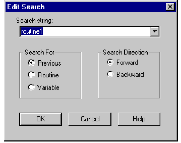
The object that is currently selected is displayed in the
Search
string combo box. You have the choice of typing in the text string to be searched
or selecting one of the symbols provided in the drop-down combo box. See Appendix B for
complete details.
Search again
You invoke the Search
Again function from the Edit menu or by pressing the F3
function key. Note that the search direction previously defined
is retained.
Replace
You invoke the Replace function from the Edit
menu or by simultaneously
pressing the Control and H keys (Ctrl+H.)
You see following dialog:
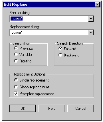
The object that is currently selected is displayed in both the
Search
string and
Replacement string combo
boxes. You have the choice of typing in the search and replacement strings or selecting one of the symbols provided in
the drop-down combo boxes. See Appendix B for complete details.
CUTTING AND PASTING
The Cut Buffer
The Cut Buffer is
a mechanism that is used to temporarily store routine statements or statement components. When you want to move or copy a statement
from the beginning of the routine to the end, for example, you first
cut or copy the statement to the Cut Buffer, move the cursor to the end of the routine,
and paste the
statement back into the routine from the Cut Buffer.
Cutting a Selected Item
To cut an item, first select the item(s) you want to cut. Then
do one of the following:
1. Select Edit/Cut
2. Enter Ctrl-X at
the keyboard
3. Select Cut from
the context-sensitive popup menu
Note that certain items, such as procedure call names and
required argument placeholders, cannot be cut.You can cut multiple statements at once by first doing a
multi-line selection.However, the following rules apply:
· You cannot cut
entire modules; you can, however cut entire routines.
· You cannot cut
multiple routines simultaneously; you must cut them one at a time.
· You cannot
select routine data declarations and executable statements together;you must cut these types of statements separately, unless you
select the entire routine.
You cannot cut incomplete statements; for example, you cannot
select and cut an IF
statement if the selection does not span to include the
ENDIF part.
Copying a Selected Item
Copying a statement or statement component to the Cut Buffer
places a copy of the item in the buffer without cutting the item from the routine.To copy an item, first select the item you want to copy. Then do
one of the following:
1. Select Edit/Copy
2. Enter Ctrl-C at
the keyboard
3. Select Copy from
the context-sensitive popup menu
Note that certain items, such as placeholders, cannot be copied.
You can copy multiple statements at once by first doing a
multi-line selection.
However, the following rules apply:
· You cannot copy
entire modules; you can, however copy entire routines.
· You cannot copy
multiple routines simultaneously; you must copy them one at a time.
· You cannot
select routine data declarations and executable statements together; you must copy these types of statements separately, unless you
select the entire routine.
Chapter 4: Program Editing
You cannot copy incomplete statements; for example, you cannot
select and copy an
IF statement if
the selection does not span to include the ENDIF part.
Pasting from the Cut Buffer
Pasting a statement or statement component from the Cut Buffer
inserts the item in the buffer back into the routine. When you paste a statement
component, the item in the Cut Buffer replaces the currently selected item; when you
paste an entire statement, the statement in the Cut Buffer is inserted before or
after the currently selected statement. See Appendix A for setting this option. To paste an item, first select an instruction to locate the
place where the contents of the Cut Buffer will be inserted. Then do one of the following:
1. Select Edit/Paste
2. Enter Ctrl-V at
the keyboard
3. Select Paste from
the context-sensitive popup menu
Note that the Paste fails if the item in the Cut
Buffer is not compatible with the selected item. For example, you cannot paste a statement into an
argument of procedure call. You can only paste an item in the Cut Buffer to
a selected item of a similar type.
DELETING ITEMS
When you delete an
item, it is permanently removed from the routine. You cannot retrieve an item after it is deleted. To avoid unwanted
deletions, you can choose to have ProgramMaker prompt you for confirmation whenever you try
to delete an item. See Appendix A for setting this option. To delete an item, first select the item you want to delete.
Then do one of the following:
1. Select Edit/Delete from the Menu Bar.
2. Press Delete at
the keyboard (this is the Edit/Delete accelerator)
3. Select Delete from the context-sensitive
popup menu
Note that certain items, such as procedure call names and
required argument placeholders, cannot be deleted. You can delete multiple statements at once by first doing a
multi-line selection.However, the following rules apply:
· You cannot
delete entire modules; you can, however delete entire routines.
· You cannot
delete multiple routines simultaneously; you must delete them one at a time.
· You cannot
select routine data declarations and executable statements together; you must delete these types of statements separately, unless you
select the entire routine.
You cannot delete incomplete statements; for example, you cannot
select and delete an IF statement
if the selection does not span to include the ENDIF part.
ProgramMaker does not permit you to make syntactical errors in
the creation of routine instructions.ProgramMaker can also help you eliminate
semantic errors that result, for
example, from referring to data or routines that have not been defined or
lie outside the scope of the current routine. Semantic errors do not prevent a program
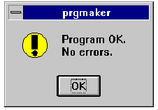
from loading,although they may cause initialization or run-time errors.To check your program for errors, select the
Check
Program command from the
Tools menu. If
your program is free of errors, you see the following message box:
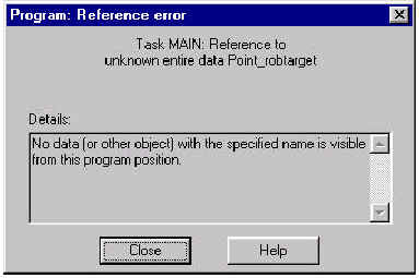
If, however, your program
contains semantic errors, the following dialog appears:
Note: This output was generated with ProgramMaker configured to
use an V3.0 version controller. The error statements generated by an earlier controller
configuration may differ significantly in content from those generated by V3.0.
The content of the message contained within the dialog will vary
greatly depending on the nature of the error. In this case, the system has pointed
out that the named parameters to the Offs()
function are undefined. The statement at which the error was encountered is highlighted in the code view, as shown below:
Note: You can change the size of the Reference Error list dialog
and place it anywhere on your screen. The next time the dialog appears on the screen, it
remembers where you last left it.
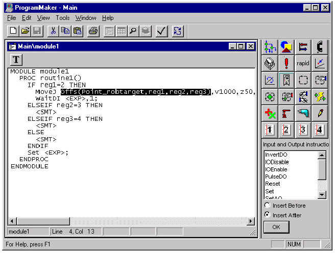
Once you have fixed the error, you should check your program
again. ProgramMaker can only identify and report one semantic error at
a time, so you may have to repeat the check several times to eliminate all semantic
errors.
When you are viewing the RAPID code within a module, the
File/Print command causes the entire module to be printed. To print an entire
program, you must first view and then print out each module individually.Note: you must have a printer defined and connected to your
system; you do this from within the Windows Control Panel. See your Windows
documentation for details.
If you have a printer defined, the standard Windows Print dialog
appears:
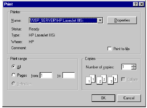
When you press OK,
the contents of the currently displayed module is sent to the printer.
Chapter 5
The Data Spreadsheet
OVERVIEW
RAPID modules basically consist of two parts: module data
declarations and routines. Routines in turn consist of three parts: the routine
declaration, the routine data declarations, and the routine body. Viewing and editing module and routine data declarations is
presented in this chapter and in Chapter
6: Viewing Data Graphically.
Viewing and editing module and routine declarations is discussed in
Chapter
3: Basic Operations. Viewing
and editing routine instructions was covered in Chapter
4: Program Editing.
VIEWING DATA DECLARATIONS
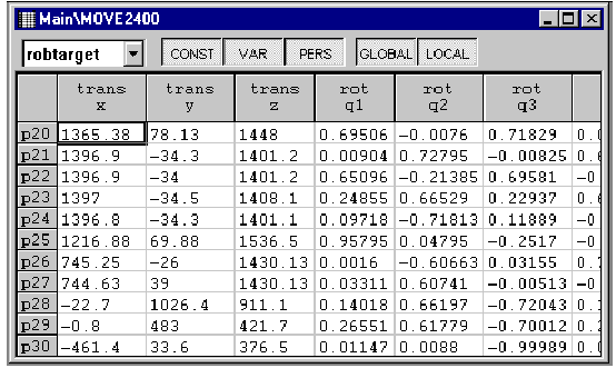
To view and/or edit module or routine data, you first select the
routine or module whose data you want to view from the Program Tree View. Next,
choose View/Data
from the Menu Bar or select the data button on the toolbar. A
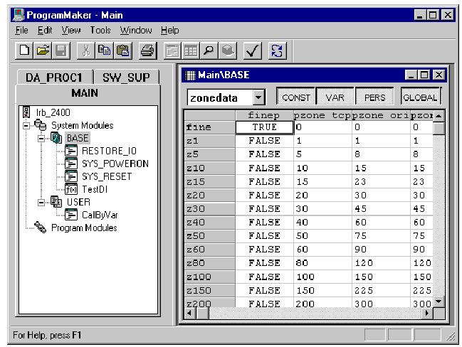
new window is created displaying the data for the module or routine, as shown.
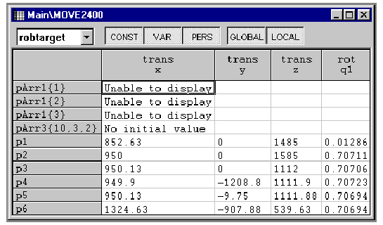
THE DATAVIEW WINDOW
The data window displays the RAPID statements that comprise the
data declarations of the module or routine as a spreadsheet. ProgramMaker can also
display robtarget
data graphically, as described in
Chapter
6: Viewing Data Graphically.
The data window caption indicates the module or module and
routine for which data is displayed. The window is composed of a spreadsheet and
toolbar. The type of data currently being displayed is indicated in the combo box on the
toolbar. Selecting a different data type in the combo box fills the spreadsheet with
the existing data of the new type found in the current scope. The spreadsheet displays the data items in the module or
routine. The data item name is in the column at the far left of the spreadsheet. The
column header for each column displays the name and the hierarchical structure of the
data component. The components that make up the data item are displayed in the
spreadsheet columns. The data can be modified directly in the spreadsheet as
described in the Editing Data
section.
Horizontal and vertical scroll bars are displayed when the data
window is too small to display all the data. You can view data items or components
that are not in the display area by using the scroll bars or control keys.
The name that appears in the data name column is the name of the
data declaration. If more than one item has the same name an instance number is
also associated with the item. In the data window, this instance number is appended
to the data name along with a separating colon. Additionally, the data window
displays a separate entry for each element in an array. The name column indicates
the array index used to access the element. This representation is shown in the
following example:
num1{2,2}; name = num1, 2X2 array
then
num1{2,1} pertains to the third element in the array
When data does not have an initial value, the structure is still
displayed with a note indicating that the data item does not have an initial value as
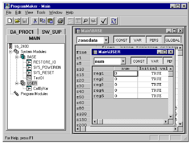
shown in the following illustration:
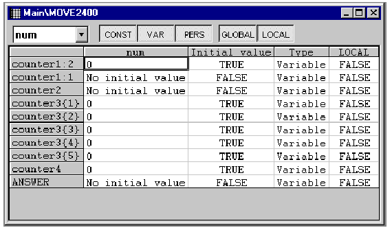
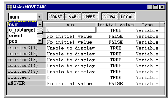
The illustration shows all of the
num data for module MOVE2400. As
the illustration indicates, counter1(instance 2), counter2, and ANSWER do not
have initial values. The counter3 and counter4 are the only
nums
that have initial values. Counter 4 has an initial value of 1000 and each element of counter 3 is 0. You
can also see from this illustration that the user has selected to show the data
properties column as evidenced by the Initial Value header. Counter3 is an array of five elements. The text "Unable to
Display" is shown when the DataView is not able to display an expression. This occurs
when the expression is not a literal or literal aggregate (contains references to
other named data).
If the Show Data
Properties option is active,
the data properties will be displayed in the far right columns of the spreadsheet as is shown in the
following illustration. If the option is not active, these columns will be hidden.
THE DATAVIEW TOOLBAR
The data window controls allow you to specify which data you
want displayed in the spreadsheet. For example, you can select the data type you wish
to display using the drop-down combo box in the toolbar as shown below:
When you have selected a new data type, the spreadsheet
refreshes, displaying all occurrences of the data type in the current module or routine.
The data type that is being displayed when the window closes becomes the default type
the next time a data window is displayed. That is, if you are displaying
zonedata when you close the window, the next data window will open with
zonedata being displayed. By default, the data type selection list displays only the data
types of items that currently exist in the module or routine. If the
Show
Most Likely data types data option is selected, the most likely data types will also be
displayed in the selection list regardless of whether there are any occurrences of the
type. The most likely data types are: bool,
num, robtarget, tooldata,
and workobj.
If the Show All Data Types
options is active, all the available types in the system appear
in the data type selection list.
The filter buttons CONST,
VAR, PERS, GLOBAL and LOCAL allow
you to selectively filter storage class and scope of the displayed data
items. Each button is a locking push-button. When you press the button it stays down
until you push it again. A selected(down) button means that this filter is active.
You select the scope of the items you wish to see displayed in the data spreadsheet(GLOBAL,LOCAL).You also select which storage classes you wish to see
displayed(CONST,VAR,PERS)
in the data window. The data that is displayed in the spreadsheet must match both the selected scope and storage
class filters. If a filter is not active, you will not see items of that type in the
data window. For instance, if only the local scope button is active, you will see
only local data in the data window. You will not see any global data.
MOVING AROUND
THE DATA WINDOW
The data window spreadsheet allows you to move through the data
using the common key and mouse controls following standard Windows
guidelines. For instance, to move to a specific cell you can either click on the
cell with the left mouse button to move there directly or you can use the tab and
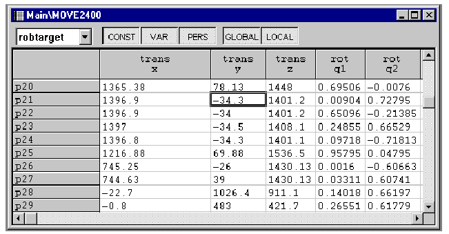
arrow keys to move through the spreadsheet. When a cell is selected, the cell
border will change to a heavy dark line ( a selection box ). If you start typing or
double-click in a cell, you will change the data in that cell. In the following
illustration, the y column cell of data item p21 is selected.
To move the selection box, you can use the mouse or a
combination of keys from the keyboard. Below is a brief summary of the navigation keys:
· Arrow keys -
the arrow keys will move the selection box in the direction of the arrow. Ctrl-Left
Arrow functions the same as the Home key, Ctrl-Right
Arrow the same
as the End key, Ctrl-Up will
move the selection box to the first row in the spreadsheet, and
Ctrl-Down
will move the selection box to
the last row in the spreadsheet.
· Tab/Shift Tab - The tab key functions the
same as the right arrow; it moves the selection box one cell to the right. The shift tab key functions
the same as the left arrow; it moves the selection box one cell to the left.
· Page Up/Page
Down - scrolls the data up or
down one page. Ctrl-Page Up will scroll the data one page left and
Ctrl-Page
Down will scroll one page
right.
· Home/End -
Home will scroll the data so the leftmost ( or first ) column is shown in the display. End will scroll the data to the rightmost
(or last) column is shown in the display.
· Shift - with
the exception of the tab key, if you hold the shift key down while using any of the movement keys or using the mouse, you will
select all the cells between the current selection and the last cell selected. The methods for selecting (useful for copying and pasting)
multiple cells are similar to other spreadsheets. When a block of cells is selected, the
entire block will be surrounded by a heavy dark line and the selected cells will be
highlighted. The current cell, or cell where the cursor is, is not highlighted
but is surrounded by the dark line. You can select a block of cells using the
Shift key with the navigation keys or by selecting a cell with the mouse and then holding the
left button down while dragging the cursor to highlight the cells you want. An
example of a selected block of data is shown in the following illustration:
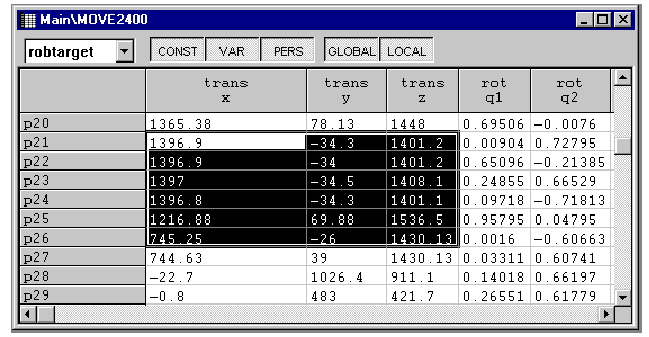
In this illustration the x, y and z cells are selected for data
items p21 through p26.
The cursor is on the x cell of data item p21.You can select an entire row by clicking on the row header (data
item name). This will highlight the entire row. You can also select an entire
column by clicking on the column header. In the following illustration, the user has
clicked on the trans y column header: 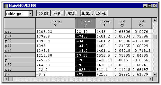
To create data, the data window must have the focus. If the data
window does not have focus, you can get the focus by clicking anywhere on the
data window, or using the Ctrl-F6 key
to switch between ProgramMaker windows. Once the data window has focus, you can create data by:
1) Pressing the Insert key on your keyboard.
1) Selecting Edit/Insert
from the Menu Bar.
1) Selecting Insert from the context sensitive
popup menu displayed by clicking the right mouse button.
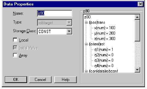
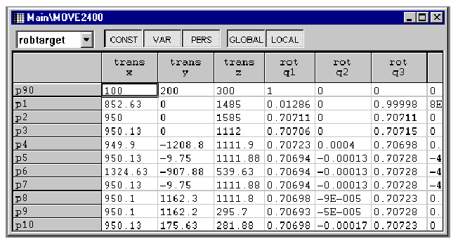
The Data
Properties Dialog appears,
displaying the declaration for the new data item, as shown:
Once you have added a new data declaration, you may edit the
component values in the same manner that previously existing data can be modified.EDITING DATA
EDITING DATA DECLARATIONS
You can edit the declaration of a data item by:
1. Double-clicking on the row header containing the data item
name.
2. Selecting any cell in the row and then choosing the
Edit/Properties in the Menu Bar.
3. Selecting any cell in the row and then choosing
Properties in the contextsensitive popup menu (that you activate by clicking the right mouse
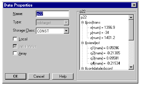
button).The Data
Properties Dialog appears, displaying the declaration of
the data item, as shown:
Note: You must save the program or module to update the program
file. Changes made to data or instructions while running ProgramMaker are only made to the
running program and not to the program file itself. To change the program file, you must
manually select Save from the File menu.
You can modify the storage class, scope, and initial value directly in the
spreadsheet as shown in the following illustration:
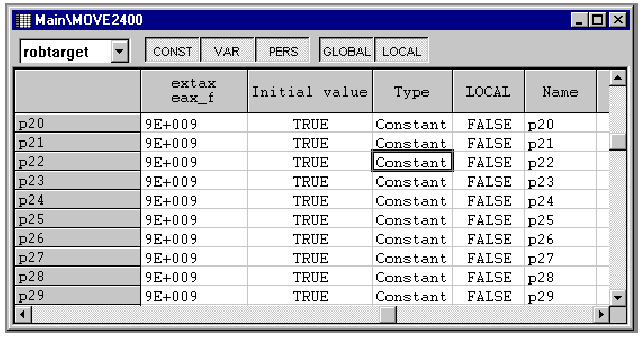
To make a change, you simply type the value you want the data
declaration to have directly into the edit box.
EDITING DATA COMPONENTS
You can edit data directly in the spreadsheet. You can do this
by either doubleclicking on the cell you wish to modify or by moving to the cell and
starting to type in the new value. Once you start to edit, the cell border
changes to a lighter cell border and a cursor appear in the selected cell. The cell
appears as shown in the
following illustration:
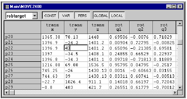
Type the value you wish the component to have. Once you leave
the cell or press the
Enter key, the
changes are automatically made to the loaded program. If you do not want to make the changes, press the
Esc(ape)
key. This will cause the original value to be displayed in the cell. Once you have left the cell, the
only way you can get the original value back is to select the cell and manually enter the
value.
CUTTING,
COPYING AND PASTING DATA
The DataView window provides two types of copying and pasting
data. You can copy and paste whole data declarations or you can copy and paste
cell data. Pasting a whole data declaration will insert a new data item(s) into the
current module or routine. Pasting cells only modifies the parameter values of
existing data items. ProgramMaker uses three different methods of copying data. It
uses the S4 cut buffer for copying and pasting entire data declarations. For copying
individual cells, it uses the Windows clipboard when copying between data windows and it
uses a special spreadsheet clipboard when copying cells inside a single data
window. Cutting copies the whole data declaration(s) to the cut buffer
in the same manner as a copy, but the data declaration(s) is also deleted from the
current module or routine. The paste action depends upon the last copy/cut action. If the
last action performed was a cut or a copy of an entire data declaration, the paste
command will cause an entire data declaration(s) to be inserted. If a copy was
performed on an individual cell or cells, a paste will affect the same range of cells as
was used in the copy.
The Clipboard
The Clipboard is
a mechanism that is used to temporarily store routine and module data. When you want to copy components of one data item to
another, you first select the block you want to copy, perform the copy, select the
destination of the block, and then paste the block of data into the data
spreadsheet.
The Cut Buffer
The Cut Buffer is
a mechanism used by the virtual controller to temporarily store routine and module data. It stores the entire data declaration,
thus allowing you to copy entire data declarations rather than individual cells.
Note: ProgramMaker does NOT check the contents of the clipboard
to determine if the contents can be pasted into the spreadsheet. It only checks the clipboard to
verify that it has contents to paste.Care must be taken when copying and pasting using the clipboard.
Copying Data to the Clipboard or Cut Buffer
Copying a cell or block of cells to the clipboard places a copy
of the item in the clipboard; the cell or block of data is not removed from the
spreadsheet. Copying a whole data record places a copy of the item in the cut buffer.
To copy an item, first select the cell(s) or data item(s) cells
you want to copy. Then do one of the following:
1. Select Edit/Copy from the Menu Bar.
2. Enter Ctrl-C at
the keyboard (this is the Edit/Copy accelerator)
3. Select Copy from
the context-sensitive popup menu
Cutting Data to the Cut Buffer
Cutting a data item to the cut buffer places a copy of the item
in the cut buffer; the data item is then removed from the spreadsheet. To cut an item, first select the row header or all the cells of
the data item you want to cut. Then do one of the following:
1. Select Edit/Cut from the Menu Bar.
2. Enter Ctrl-X at
the keyboard (this is the Edit/Cut accelerator)
3. Select Cut from
the context-sensitive popup menu
Pasting Data
Pasting individual cells inserts the data into the selected area
of the spreadsheet.Pasting an entire data item inserts a new data declaration into
the current module or routine.Once data has been placed in the clipboard or cut buffer, you
can paste the data by doing one of the following:
1. Select Edit/Paste from the Menu Bar.
2. Enter Ctrl-V at
the keyboard (this is the Edit/Paste accelerator)
3. Select Paste from
the context-sensitive popup menu
If individual cells were copied, the clipboard contents are
pasted into the spreadsheet depending on the size of the selected range.
· If the selected
range consists of a single cell, the entire contents of the clipboard are pasted into the spreadsheet.
· If the selected
range is smaller than the contents of the clipboard, only the data that will fit in the selected range is pasted.
· If the selected
range is larger than the contents of the clipboard, the clipboard contents are replicated to fill the entire selected range.
Note: The spreadsheet can paste tab-delimited blocks of data
from the clipboard.
DELETING DATA
When you delete a
data item, it is permanently removed from the module or routine. You cannot retrieve a data item after it is deleted. To avoid
unwanted deletions, you are prompted for confirmation whenever you try to delete an item
unless you have disabled the confirmation using
the
Confirm On Delete option. To delete an item, first select the data item you want to
delete. You must select the entire item by clicking on the row header or by selecting every
cell in the row.
1. Select Edit/Delete from the Menu Bar.
2. Press Delete at
the keyboard (this is the Edit/Delete accelerator).
3. Select Delete from the context-sensitive
popup menu.
You can select a block of data items to delete. You are not
allowed to delete multiple blocks of data items at the same time. You cannot
delete specific cells of a data item. The options available
include the data types displayed in the drop down combo box and whether or not the data
declaration properties are displayed in the spreadsheet.To print the data of a module or routine to a printer, select
the File/Print command from the Menu Bar or Tool Bar. Note: you must have a printer
defined and connected to your system; you do this from within the Windows
Control Panel. See your Windows documentation for details.If you have a printer defined, the standard Windows Print dialog
appears:
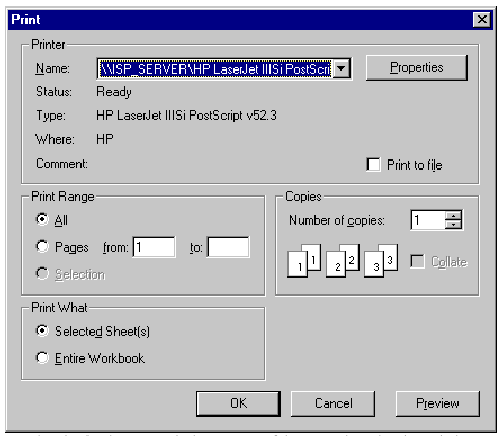
Pressing the OK button
sends the contents of the currently active data window to the printer.
Chapter 6
The Graphical View
The GraphView is a tool that makes it easier to get an overview
of your module or routine and to edit the positions.Viewing and editing positions in modules and routines through
three-dimensional (3D) graphics is presented in this chapter.
Chapter
5: The Data Spreadsheet presents a spreadsheet method of viewing and editing general module and
routine data declarations. Chapter
4:Program Editing presents
methods for viewing and editing entire modules.The GraphView displays a three-dimensional (3D) graphical view
of the position data and the path. The window title shows the name of the currently selected module
or routine.
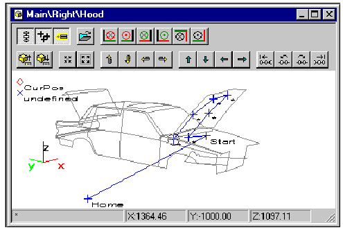
The GraphView has a resolution of 1 mm. The GraphView can show
positions within the range -6000 mm to 6000 mm.
SELECTING A ROUTINE OR MODULE
You can display the positions of a module or routine by:
Select the module or routine in the Program Tree. Then choose
the View/Graph
from the Menu Bar or select the
Graph button on the ProgramMaker’s
main toolbar. You could, alternatively, select the module or routine in the
Tree View by right clicking on it, followed by choosing the
View
Graph command from the popup menu.
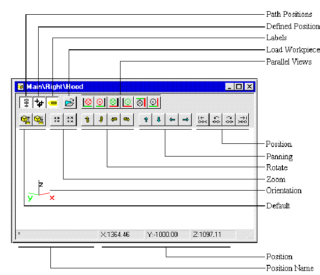
A triad showing the rotation of the graphical view is displayed
at all times in the lower left corner of the GraphView.
The X vector is red, Y is green and Z is black
You can change the view by using the toolbar functions: Zoom,
Rotate, Panning and Parallel views.
POSITIONS DISPLAYED IN THE
GRAPHVIEW
You can select to view a module or a routine in the GraphView
The content of the GraphView when displaying a module are the
defined positions within the data declaration section of that module.
The content of the GraphView when displaying a routine are the
defined positions within the data declaration section of that routine and all
positions used within the routine.
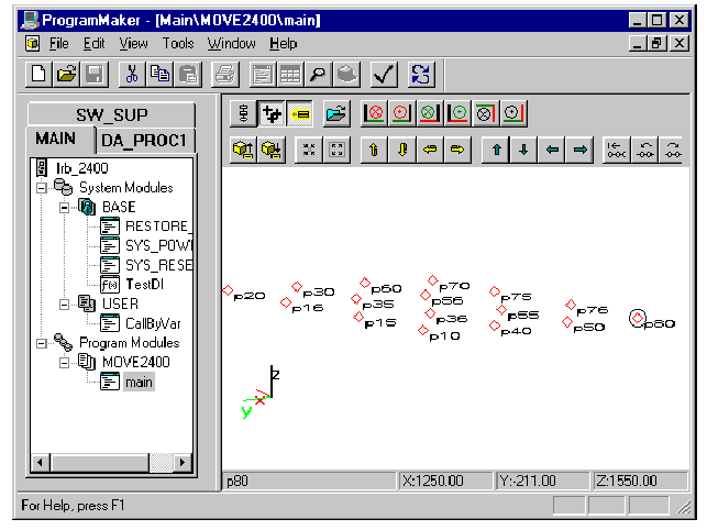
Display Defined Positions
The positions defined in the data declaration section of the
selected module or routine are displayed as red diamonds .
The defined positions are drawn according to their initial
values. Variable data declarations without initial values are drawn in the left corner
of the view.
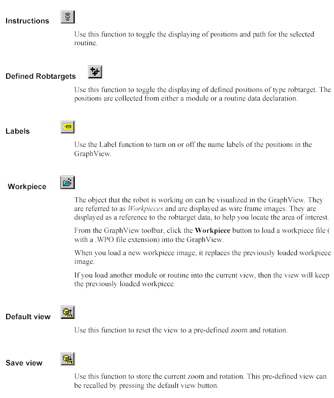
You can turn on or off displaying of the defined positions by
clicking the Defined
Robtargets
toolbar
button.
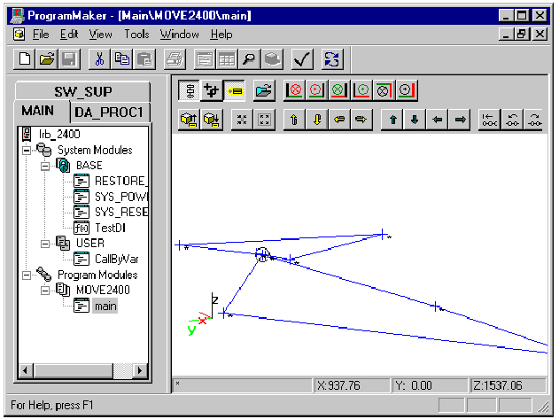
Display Instructions with path
The GraphView can display the path and the positions referenced
by the RAPID instructions of a selected routine.
The positions referenced by the following instructions are
drawn:
MoveL,
MoveJ, PaintL, SearchL, TriggL,
TriggJ, MoveC, PaintC, SearchC and
TriggC.
The resolved positions, named positions with initial values and
positions defined directly in the instruction, are drawn as crosses . All other
positions referred to in the instructions are drawn as x-crosses in the left corner of
the view.The path is drawn from a resolved position at one line of RAPID
if the next RAPID line is one of the instructions
MoveL, MoveJ, PaintL, SearchL,
TriggL and
TriggJ.All positions are assumed to be relative to the same work object
(coordinate system).You can turn on or off displaying of the instructions by
clicking the Instructions
toolbar button.
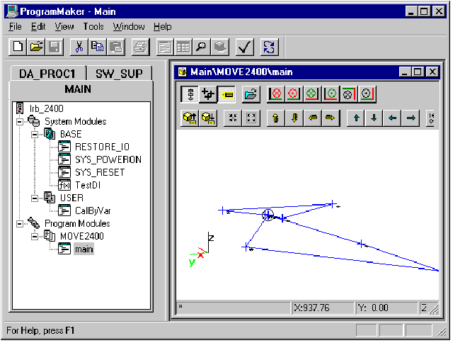
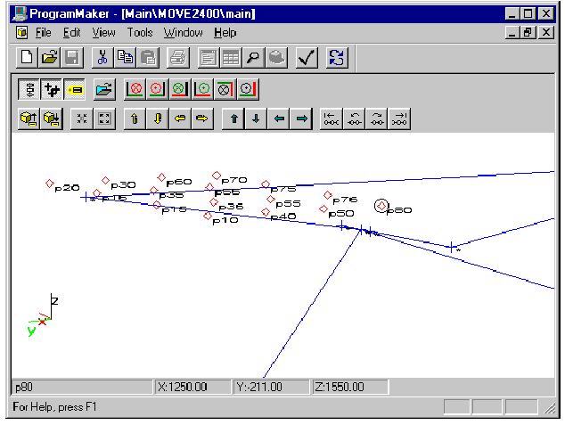
The following diagram shows both the defined data and the path
in the routine main
(the program tree has been hidden and the view expanded to show
both types of display).
The GraphView has the capability of editing your program’s
positions. The view provides context-sensitive links from the selected graph element
to the
Data
Properties Dialog
or
the Procedure Call Dialog.
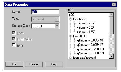
EDITING DEFINED POSITIONS
Editing a defined position is done by: double-clicking on a
defined position , or by right-clicking at a referenced position or and then selecting
Data
Properties
from the pop-up menu. The
Data Properties Dialog appears
for you to make your changes.
EDITING INSTRUCTIONS
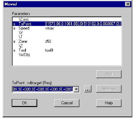
Editing the instructions of your routine is done by
double-clicking on a referenced position or . The Procedure
Call Dialog appears for you to
make changes.
Use these functions to focus in on a specific part of the
robtarget data or to get an overview of the program shown in the GraphView.Zoom out makes the view smaller.
Zoom in makes the view larger.

Rotate
You use the rotate functions in the GraphView toolbar to rotate
the program robtarget data shown in the GraphView. (It will also change the
view from parallel to perspective.) The triad (X, Y, Z) in the lower left corner of
the window shows the current orientation.

Panning
You use the pan (shift) function in the GraphView toolbar to
move the robtarget data shown in the GraphView up, down, left or right.

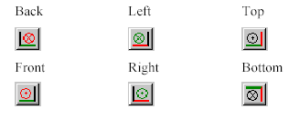
Parallel views
These functions in the GraphView toolbar are used to select one
of the six ISO parallel views. They change the view from perspective to
parallel view.
The currently selected graph element is marked with a circle. A
graph element is a single robtarget data. A graph element can be selected by
clicking on it or by using the Previous/Next-point buttons in the GraphView toolbar.

The file format of a workpiece image is a plain ASCII text file
using tab delimited values for X, Y, Z and a flag telling if the line is visible or
not. If the flag is 0 a line is drawn from the previous point to this point. However, a flag
value equal to 1 results in an invisible line.The lines must be separated with the ASCII characters
representing <carriagereturn> and <newline>.Any line that starts with a number is interpreted as a workpiece
point. If any of the other values are not a numeric, the default value 0 is used for
that value and the rest of the values on that line.You can add comments to the workpiece files. A comment is any
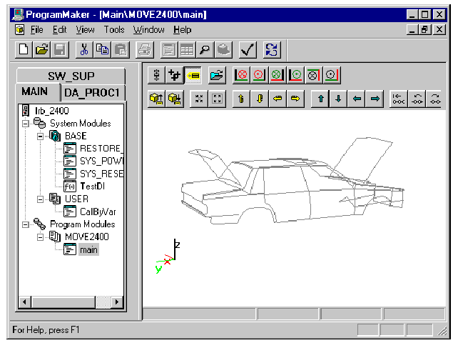
line that does not begin with a number. The file extension for workpiece files are ".WPO".The following GraphView window shows a loaded
workpiece.
CREATING AND EDITING
WORKPIECE FILES
You can create and edit workpiece files using the
WorkPieceMaker utility. You run this utility from ProgramMaker.
To do this, select the
Tools/Utilities/WorkPieceMaker menu
item. See the WorkPieceMaker help
file for more information on using this tool.Alternatively, it is possible to use Windows Notepad editor to
create or modify workpiece image files, as long as the workpiece image file
format is used.It is possible to copy robtarget data from the spreadsheet data
into Notepad to make a workpiece from robtarget data


